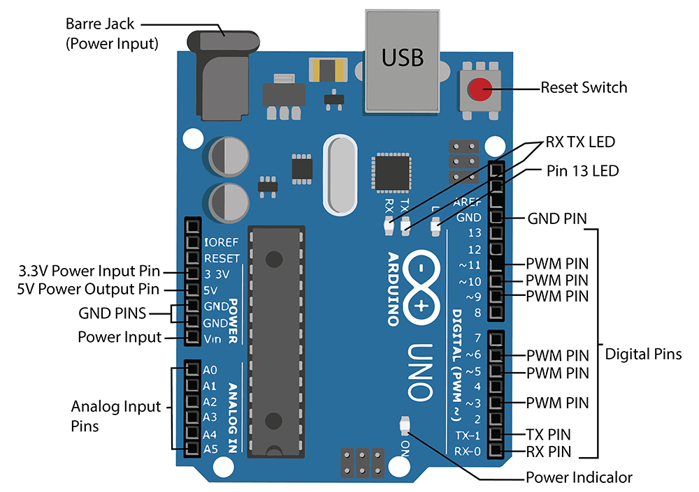

Vin: The input voltage or Vin to the Arduino while it is using an exterior power supply opposite to volts from the connection of USB or else RPS (regulated power supply).

The power pins of an Arduino board include the following. The battery terminals can be placed in the pins of Vin as well as GND. The connection of an adapter can be done by plugging a center-positive plug (2.1mm) into the power jack on the board. The exterior power supply (6 to 20 volts) mainly includes a battery or an AC to DC adapter. The power supply of the Arduino can be done with the help of an exterior power supply otherwise USB connection. This board includes 14 digital input/output pins, Analog inputs-6, a USB connection, quartz crystal-16 MHz, a power jack, a USB connection, resonator-16Mhz, a power jack, an ICSP header an RST button. From these pins, 6-pins can be utilized like PWM outputs. The Arduino Uno R3 pin diagram is shown below. The weight of the Arduino board is 25 g.Length and width of the Arduino are 68.6 mm X 53.4 mm.Flash Memory -32 KB, and 0.5 KB memory is used by the boot loader.The recommended input voltage ranges from 7V to 12V.The Operating Voltage of the Arduino is 5V.It is an ATmega328P based Microcontroller.So keeping in mind these changes, we can chalk down the final list of components. So I will be placing to rows of header, one male and one female around the board which will help me to connect more number of devices directly to the arduino. The last thing I want on my board is ample number of power lines and two headers for each IO ports.So LM1117 should be a obvious choice here, but to keep the making cost even lower, we will be using LM317 with R1 and R2 as 240E and 390E respectively. But due to unavailability of the board in TH format, we will be using a simple linear regulator. The tradition one uses a LP2985 IC from Texas Instruments to get the 3.3v power supply on board.But in our version we will be manually switching that using a jumper. Original arduino uses a mosfet comparator to determine whether we are powering up the board with a usb power supply or a DC-in.A separate FTDI breakout board will be used to program the new arduino. I didn't find any FTDI chip in through hole format, so the USB to TTl conversion will not be done on board.All the items will be in through hole format. As I have told earlier, I will not be using any SMD components on board.
#Diagram of arduino uno download
Let's start the tutorial.įirst of all let's talk about the changes that I am gonna make in the original Arduino Uno schematic that you can download form the link below. You will be sorted.Īlso if you like this tutorial then follow us on this page "Being Engineers" and check out our youtube channel. I have also made a detailed video discussing the whole process in youtube, so if you don't feel like reading the whole doc here, watch that video. Moreover through hole components are cheaper than SMD components in most of the cases. But before starting let me tell you that I will not be using any SMD components to make my version of arduino because not everybody has a soldering station and sometimes, specially here where I live, finding SMD components is harder.

So in this tutorial we will be looking into the schematic of Arduino Uno, modify it a little to our needs, make a PCB out of it and solder the required components to make the final product. Now it being a open source platform it's quite easy to get to know about the insides and the bits and pieces of all the things that makes arduino what it is. WIthout arduino this channel might not even started at all. Before starting this let me thank the whole arduino community for the immense support they has provided us throughout the time. This is kind of a updated version of that.
#Diagram of arduino uno series
A year ago I have made a series of tutorials about homemade DIY arduino. In today’s tutorial I will show you how I made my own arduino uno board using the atmega328p IC.


 0 kommentar(er)
